

Drip irrigation — also termed micro-irrigation or trickle irrigation — is the practice of delivering water directly to the root zone of plants through a network of pressurised pipes, sub-mains, laterals, and low-flow emitters. Unlike flood irrigation, which saturates entire field surfaces, drip systems target soil moisture only where it is agronomically effective, minimising deep percolation, surface run-off, and evaporative losses. The technology has evolved from subsurface clay-pot practices documented in China’s Fan Shengzhi shu (first century BCE) to the plastic-emitter systems first commercialised in Israel in the 1960s, and today represents what researchers have characterised as the most efficient means of applying water to crops (Pathak et al., 2009; Goyal, 2012).
As of 2023, approximately 3% of the world’s farmers employ drip irrigation. The pace of adoption is accelerating in response to freshwater scarcity, regulatory pressure to reduce agricultural runoff, and the growing economic case for input efficiency. A meta-analysis drawing on 352 studies in China alone found that water–fertiliser integrated drip irrigation (WFIDI) consistently delivers water savings and yield increases exceeding 20% compared to conventional methods. This article synthesises research findings on agro-hydrological benefits, the engineering taxonomy of emitter types, and the industrial manufacturing processes and cost structures involved in dripline production.
The core hydrological advantage of drip irrigation is its application efficiency. Whereas conventional sprinkler systems direct only 65–75% of applied water to the root zone, well-designed drip systems achieve efficiencies of approximately 90%. A three-year field study on sugarcane in Upper Egypt (published in Applied Water Science, Springer, 2025) recorded a 44% reduction in water consumption — from 11,280 to 7,920 m³/acre/year — compared to flood irrigation, while simultaneously increasing yield by 22%. These values are consistent with a broader literature consensus: drip irrigation reduces water input by 30–50% relative to surface flooding, depending on soil type, crop, and climate (Liu et al., 2013; Zhang et al., 2011).
A 2024 review in Water (MDPI) confirmed that compared with traditional irrigation, drip irrigation significantly decreases water consumption by reducing soil surface evaporation and preventing deep percolation losses. The same review noted that strategic irrigation timing — particularly early-morning application between 04:00 and 09:00 — can further reduce evaporative losses by as much as 30%, cutting total system water use by an additional 15–30%.
When drip irrigation volumes are set at 100–120% of crop evapotranspiration demand, meta-analysis data show statistically significant yield increases relative to competing irrigation methods: +28.92% over flood irrigation, +14.55% over border irrigation, +8.03% over furrow irrigation, +2.32% over sprinkler irrigation, and +5.17% over micro-sprinkler irrigation (MDPI Water, 2023). For maize specifically, a 2025 review published in Field Crop (Crop Science Publisher) found that drip fertigation improves water use efficiency by 20–50% and increases nutrient use efficiency by more than 30% relative to traditional irrigation and surface fertilisation.
The mechanism is partly physiological: by maintaining soil moisture within an optimal range and supplying nitrogen in dissolved form to the root zone, drip fertigation promotes leaf area index development, photosynthetic efficiency, and the accumulation and transfer of dry matter. Studies on subsurface aerated drip irrigation — a newer variant that injects air microbubbles into the irrigation stream — have recorded increases in dry matter accumulation of 42.0%, photosynthetic rate of 868.6%, stomatal conductance of 157.1%, and transpiration rate of 55.6% compared to non-aerated treatment in Chinese cabbage (MDPI, 2023).
Key finding: Drip fertigation can save 30–40% of irrigation water, increase crop yields by 5–20%, improve water use efficiency by 20–50%, and increase nutrient use efficiency by more than 30% (Crop Science Publisher, 2025).
The co-delivery of water and soluble fertiliser through the irrigation network — termed fertigation — is one of the most significant secondary benefits of drip systems. Because nutrients are applied directly into the active root zone at the moment of water uptake, leaching to groundwater is substantially reduced. A ScienceDirect meta-analysis on water–fertiliser integration found that nitrogen loss is reduced by 25–50% under drip fertigation relative to broadcast surface application (Yi, 2018). The harvest rate of crops rises from the 60–70% typical of traditional irrigation to approximately 90% under WFIDI protocols.
The environmental implications are considerable. WFIDI has been shown to limit atmospheric N₂O emissions — a greenhouse gas with a global warming potential approximately 273 times that of CO₂ — as well as reducing soil erosion and nitrogen leaching. These benefits have contributed to WFIDI adoption in more than 80 countries across food staple and cash crop production systems.
Conventional flood irrigation can cause salinisation of topsoil through the capillary rise and evaporation of saline groundwater. Drip irrigation under plastic film maintains controlled moisture in the root zone and has been documented to control soil salinity in the top 140 cm of the soil profile during the growing season (Wang et al., 2014, cited in ScienceDirect Topics). This is particularly significant in arid and semi-arid regions such as the Xinjiang plains of China, the Nile Valley, and the Central Asian steppes, where secondary salinisation has rendered large areas of formerly productive land unfit for cultivation.
However, it should be noted that while drip irrigation reduces salt accumulation in wetted zones, non-irrigated inter-row areas can accumulate salts over time. Long-term field trials recommend periodic leaching events to manage this redistribution effect, particularly in regions with annual rainfall below 200 mm.
The emitter — also called a dripper — is the hydraulic terminal device through which the dripline delivers water to the soil. It is the most hydraulically critical component of the entire irrigation system: its internal flow path geometry determines flow rate, uniformity coefficient (Cv), and clogging resistance. This article describes the engineering principles underpinning the three families of A.A.S. emitters — Turbulent Flow, Pressure Compensating (PC), and the Cu Copper-Infused Emitter Line.
The flow path is the most important element in emitter design. Its width, depth, and length determine the flow rate in litres per hour, and — more critically — the anti-clogging ability of the emitter. A highly turbulent flow design creates multiple vortices inside the flow path, keeping particles in suspension and preventing them from settling or adhering to the channel walls.
All A.A.S. Advanced Automation Systems Ltd emitters are injection-moulded from the finest raw materials that provide durability and long-lasting performance, and achieve a Coefficient of Variation (CV) of less than 5%. This means that the statistical spread of flow rates across a production batch is tightly controlled, which translates directly into high field emission uniformity — ensuring every plant in an irrigated zone receives a consistent water supply. An advanced three-dimensional water inlet design, used across multiple A.A.S. emitter models, increases the filtering area at the entry to the flow path, enhancing anti-clogging performance by preventing particles from entering the labyrinth in the first place.
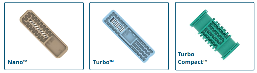
The Turbulent Flow family comprises emitters that deliver water at a rate determined by operating pressure, without pressure compensation. The absence of a membrane mechanism makes them cost-effective and highly reliable in flat terrain and stable-pressure systems. All three models in this family share the core AAS turbulent labyrinth architecture — wide, accurate water passages that generate high turbulence for clogging resistance — and achieve CV below 5%.
The Nano™ is AAS’s most compact flat turbulent emitter, specifically engineered for thin and medium wall dripline applications where weight and dimensions are commercially significant. Its curved-edge design produces a very low kd (drag coefficient) factor, resulting in extremely low friction losses for water flowing inside the dripline — a property that enables the very high production speeds achievable on the N350 FL production line. The ultra-compact design means finished coils contain more metres for the same outer dimensions, reducing logistics costs per metre compared to conventional thin-wall tape products.
The Nano™ is available in four flow rates: 0.6, 1.0, 1.6, and 2.0 litres per hour. It is compatible with driplines of any diameter from 12 mm upwards and supports wall thicknesses from 5 mil to 12 mil (0.127–0.3 mm). Emitter spacings can be set from as close as 10 cm, which is particularly valuable for high-density vegetable production. Applications include row crops, vegetables, and both surface and shallow subsurface installations depending on wall thickness.
Key specifications — Nano™: Flow rates 0.6 / 1.0 / 1.6 / 2.0 l/h | Wall thickness 5–12 mil (0.127–0.3 mm) | Min. dripline diameter 12 mm | Min. spacing 10 cm | CV < 5%
The Turbo™ is described by AAS as one of the world’s most proven and trusted flat emitters, with more than 30 years of documented use in surface and subsurface applications worldwide. Its symmetrical design allows the highest insertion rates and correspondingly higher production speeds during manufacturing. The highly turbulent labyrinth features a large cross-section, ensuring superior clogging resistance across its wide operating range. An advanced water inlet design increases filtering area and prevents particle insertion into the emitter, complementing the turbulent-flow anti-clogging mechanism.
The Turbo™ offers the broadest flow rate range in the turbulent flow family: 0.8, 1.3, 1.6, 2.0, 2.4, and 3.8 litres per hour. It is designed for wall thicknesses from 5 mil to 47 mil (0.13–1.2 mm), making it uniquely versatile across both disposable single-season thin-wall tape and durable thick-wall multi-season dripline. It is suitable for driplines from 12 mm diameter upwards, and is appropriate for row crops, orchards, landscaping, vegetables, and gardening, in both surface and shallow subsurface installations.
Key specifications — Turbo™: Flow rates 0.8 / 1.3 / 1.6 / 2.0 / 2.4 / 3.8 l/h | Wall thickness 5–47 mil (0.13–1.2 mm) | Min. dripline diameter 12 mm | CV < 5%
The Turbo Compact™ is the cylindrical member of the turbulent flow family, designed for insertion into round-profile thick-wall dripline. It is described by AAS as a compact and economical emitter for a wide range of applications, and as particularly suitable for permanent crops, multi-season usage, and farmers new to drip irrigation due to its robust, straightforward operation. The emitter offers high UV resistance and very high resistance to agrochemicals and hard field conditions, properties that are essential for long-term outdoor deployment. Its labyrinth design generates high turbulent flow, while the advanced water inlet prevents particle entry.
The Turbo Compact™ is available in two flow rates — 2.0 and 4.0 litres per hour — and is designed for 16 mm diameter dripline with wall thicknesses of 25–47 mil (0.65–1.2 mm). It is suitable for both surface and subsurface installations across row crops, orchards, landscaping, vegetables, and gardening. On the production side, it is the cylindrical emitter compatible with the R120 CL production line.
Key specifications — Turbo Compact™: Flow rates 2.0 / 4.0 l/h | Wall thickness 25–47 mil (0.65–1.2 mm) | Dripline diameter 16 mm | CV < 5%

PC emitters incorporate a silicon membrane that enables the delivery of a precise and equal volume of water across a broad pressure range. As inlet pressure rises, the membrane deforms progressively to narrow the exit orifice, maintaining a near-constant output regardless of pressure fluctuations along the lateral. This technology allows the use of drip irrigation in inclined topography and in conditions where the precise delivery of a specific water volume is agronomically mandatory. All AAS PC emitters also feature a continuous self-cleaning mechanism that ensures non-clogging, uninterrupted operation throughout the irrigation cycle.
AAS PC emitters are available in three configurations — Drain (D), Non-Drain (ND), and Anti-Siphon (AS) — across multiple models. The Non-Drain system keeps the dripline full of water during irrigation intervals, ensuring immediate and uniform flow when irrigation resumes; the emitter closes when pressure drops below 0.1 bar, eliminating the drainage and refill effect and improving efficiency in pulse irrigation. The Anti-Siphon system prevents suction of soil, dirt, and impurities back into the emitter during system shut-off, which is the critical enabling technology for subsurface drip irrigation (SDI).
The Cyclone PC™ is AAS’s flagship flat pressure-compensating emitter: an ultra-slim, high-tech design that fits any hose diameter. The two-part emitter body is sealed using state-of-the-art laser welding technology, which ensures flawless operation under any condition and prevents leaks even in the event of extremely high pressures or emitter opening during dripline installation or retraction. The ultra-slim geometry results in low friction losses for water flowing inside the dripline and enables the high production speeds achievable on AAS flat dripline production lines. The Cyclone PC™ is designed for precision irrigation needs and inclined topography.
Available in five flow rates — 1.0, 1.5, 2.0, 2.4, and 3.8 litres per hour — the Cyclone PC™ is designed for wall thicknesses from 12 mil to 47 mil (0.3–1.2 mm) and for driplines with an internal diameter from 13.5 mm upwards. It is offered in Drain, Non-Drain, and Anti-Siphon variants; the AS option enables reliable SDI installation. Applications include precision irrigation, uneven terrain, greenhouses, orchards, and pulse irrigation, in both surface and subsurface configurations.
Key specifications — Cyclone PC™: Flow rates 1.0 / 1.5 / 2.0 / 2.4 / 3.8 l/h | Wall thickness 12–47 mil (0.3–1.2 mm) | Min. ID 13.5 mm | Laser welded | D / ND / AS variants | CV < 5%
The Triton PC™ is described by AAS as the most durable pressure-compensating emitter in their range, engineered for the harshest agronomic environments: steep and rocky terrain, permanent crops with long laterals, and multi-year on-surface and subsurface installations. Like the Cyclone PC™, it incorporates a silicon membrane for precision pressure compensation, a special labyrinth design that generates high turbulent water flow, and a continuous self-cleaning mechanism. It is noted as excellent for effluent water reuse applications, where biological and particulate loading can challenge lesser emitter designs.
The Triton PC™ is available in two flow rates — 2.0 and 4.0 litres per hour — and is designed for 16 mm diameter dripline with wall thicknesses of 25–47 mil (0.65–1.2 mm). Drain, Non-Drain, and Anti-Siphon options are available; the AS system enables full SDI functionality. It is compatible with the R120 CL cylindrical dripline production line and is suited to precision irrigation, uneven terrain, row crops, orchards, landscaping, gardening, and pulse irrigation.
Key specifications — Triton PC™: Flow rates 2.0 / 4.0 l/h | Wall thickness 25–47 mil (0.65–1.2 mm) | Dripline diameter 16 mm | D / ND / AS variants | CV < 5%
The Aquarius PC™ is AAS’s online pressure-compensating emitter: the most versatile and easy-to-install PC emitter in their range, covering applications from home gardens to the most advanced hydroponic installations. Unlike inline emitters, which are integrated into the dripline pipe wall during production, the Aquarius PC™ is installed manually by the end user at any point on a pipe using a barbed piercing fitting, allowing individual emitter placement to be adjusted to match plant location, tree growth rate, or changing system requirements.
The emitter body and cover are joined by ultrasonic welding technology — a parallel-formation weld around the entire edge of the body — which eliminates the leakage between body and cover that is a known failure mode in conventional online emitters under variable climatic or pressure conditions. The Aquarius PC™ features a cross-shaped water inlet, wide and accurate labyrinth passages, and a continuous self-cleaning mechanism. It operates across a pressure compensation range of 0.5 to 4.0 bar and supports manifold outlet configurations with multiple outputs via a single type of outlet compatible with 3 mm internal diameter micro-tube and press-fit nipple connectors.
Available in four flow rates — 2.0, 4.0, 8.0, and 24 litres per hour — and in Drain and Non-Drain variants, the Aquarius PC™ is designed for installation in pipes from 12 mm to 32 mm diameter with wall thicknesses of 0.9–1.2 mm (35–47 mil). Applications include orchards, greenhouses and nurseries, gardening, landscaping, hydroponics, soilless culture, and pulse irrigation.
Key specifications — Aquarius PC™: Flow rates 2.0 / 4.0 / 8.0 / 24 l/h | Pressure range 0.5–4.0 bar | Pipe diameter 12–32 mm | Wall thickness 35–47 mil | Ultrasonic welded | D / ND variants | CV < 5%

Subsurface Drip Irrigation (SDI) is regarded as the most efficient irrigation method, since it delivers water directly into the root zone of plants through a network of buried driplines, eliminating surface evaporation entirely and minimising weed germination on non-irrigated inter-row strips. However, SDI systems face two specific biological threats that do not affect surface-installed driplines: root intrusion into the emitter outlet, and the development of algae, bacteria, and fungi within the emitter flow path, fuelled by the warm, moist, biologically active soil environment.
The Cu Emitter Line™ from AAS is a comprehensive solution specifically engineered for SDI applications. All four Cu emitters incorporate a copper oxide compound within the emitter material. Copper oxide is a well-established biocidal agent: it prevents root intrusion into the emitter while simultaneously inhibiting the growth of algae, bacteria, and fungi inside the emitter, eliminating two of the primary long-term failure mechanisms of SDI systems. In conjunction with the Anti-Siphon (AS) system — available on Cu Cyclone PC™ and Cu Triton PC™ — which prevents suction of soil and impurities into the emitter during shut-off, the Cu Emitter Line™ provides a complete dual-mechanism protection system for buried dripline installations.
The Cu Cyclone PC™ combines the ultra-slim flat PC design and laser welding technology of the standard Cyclone PC™ with copper oxide infusion and the Anti-Siphon option. It is described by AAS as providing high irrigation accuracy and consistent clog-free performance through the combination of the copper oxide compound and anti-siphon technology. It fits any hose diameter and is designed for SDI applications where both root intrusion resistance and high emission uniformity are required.
The Cu Triton PC™ is the cylindrical PC emitter in the Cu line, described as the most durable pressure-compensating emitter in the range, designed for permanent crops with long laterals and multi-season subsurface applications. As with the standard Triton PC™, it is built for steep and rocky terrain and suitable for effluent water reuse; the addition of copper oxide infusion extends its suitability to deep buried applications where root pressure and biological activity in the soil are significant long-term concerns.
The Cu Turbo™ is described by AAS as the most successful flat emitter in their range, developed for a wide range of shallow and deep buried subsurface applications. It carries the full turbulent-flow anti-clogging architecture of the standard Turbo™ — wide labyrinth passages, high turbulence, advanced water inlet — with the addition of copper oxide infusion to address the biological challenges specific to SDI environments.
The Cu Turbo Compact™ is the most durability-oriented emitter in the Cu line: a compact and extremely robust cylindrical turbulent emitter developed for a wide range of deep buried, multi-season subsurface applications. AAS specifies a service life of more than 15 years depending on dripline thickness, making it the appropriate choice for capital-intensive permanent-crop SDI installations where system replacement is not planned within the lifetime of the orchard or vineyard.


A dripline production line is a continuous, multi-station extrusion system that simultaneously forms the polyethylene pipe, inserts pre-manufactured emitters at programmed intervals, perforates the pipe wall at each emitter outlet, and coils the finished product. The principal components of a flat dripline or round pipe production line are: the extruder, cross-head die, vacuum and cooling tank, dripper feeding and sorting system, dripper inserting unit, perforating (drilling) unit, haul-off machine, and coiler. Each station is mechanically and electronically synchronised to maintain precise emitter spacing and outlet hole alignment at production speeds that, on leading systems, exceed 250 metres per minute.
The extrusion stage melts and homogenises the polyethylene resin compound — which includes HDPE or LLDPE base resin, UV stabiliser, carbon black (for opaque UV-protective formulations), and antioxidant additives — before forcing it through a cross-head die to form the tubular pipe profile. For flat drip tape, the extruder output must be precisely controlled to maintain consistent gram-per-metre weight, as wall thickness variations directly affect emitter fit and hydraulic performance. Advanced production lines apply servo-driven haul-off machines that synchronise line speed with the extruder output, enabling stable gram-weight control throughout the production run. A 3-layer co-extrusion variant — in which the inner and outer layers (totalling approximately 20% of material) are produced from virgin PE resin, while the core layer (80%) may utilise recycled or off-specification material — reduces raw material costs while maintaining external surface and bore quality specifications.

Pre-manufactured emitter chips are fed from bulk hoppers through a centrifugal sorting and orientation system that ensures each emitter arrives at the insertion head in the correct physical orientation. The design of this sorting system is a significant determinant of achievable insertion rate: a feeding bottleneck at the sorter limits the overall production line speed. Advanced centrifugal feeder designs, enhanced by AI-driven parameter optimisation, can sustain supply rates of up to 2,500 emitters per minute on leading flat tape production lines. The inserting unit then registers each emitter against the pipe bore and presses it into the interior of the freshly extruded pipe, which is still at a temperature slightly above its softening point, allowing a positive mechanical weld between emitter and pipe inner wall. Emitter spacing — typically 10 to 50 cm — is programmable via PLC, enabling a single production line to produce multiple SKUs without mechanical retooling.
Once the emitter is inserted, a perforating unit punches the water outlet hole through the outer pipe wall at the precise location of each emitter outlet port. Punch-hole registration accuracy is critical: misalignment between the hole and the emitter outlet impedes flow and increases the risk of particulate ingress. High-speed perforators on modern lines use servo-driven robotic actuation combined with optical vision systems to verify hole position and flag non-conforming sections for automatic rejection and waste-pipe separation.

After extrusion and emitter integration, the pipe passes through a vacuum calibrating tank and subsequent water cooling baths to set the final pipe geometry and temper the polyethylene. The vacuum tank applies external sub-atmospheric pressure against the softened pipe surface to maintain dimensional accuracy. The haul-off machine provides the tensile pull that draws pipe from the die at a controlled speed matched to the extruder output. The coiler winds finished pipe onto spools or into lay-flat coils of specified lengths. Automatic coilers with robotic core-loading and accumulator buffering allow continuous operation through coil changeovers without reducing line speed.
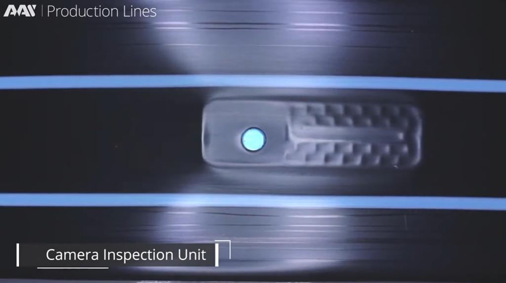
Modern production lines integrate continuous quality monitoring systems. These include laser dimensional gauges that measure outer diameter and wall thickness at multiple points per second, optical hole-inspection vision systems that verify perforation position and dimensions at full production speed, and dripper flow testing equipment that samples emitter discharge at configurable intervals. Production data — including line speed, gram-weight, emitter spacing, and QC rejection rates — are logged to PLC-based MES (Manufacturing Execution Systems) for traceability and process optimisation. Statistical process control (SPC) algorithms monitor key parameters and alert operators to drift before out-of-specification product accumulates.
The latest generation of dripline production technology has moved beyond fixed-parameter PLC control to incorporate artificial intelligence at the process level. AI-driven software continuously analyses signals from sensors distributed across the production line, detects deviations from optimal process parameters, and applies dynamic micro-corrections to critical variables — including haul-off speed, emitter sorter parameters, and perforation timing — without operator intervention. A.A.S. Advanced Automation Systems Ltd , a globally active producer of emitters and production lines for the drip irrigation industry, has been noted as the first company in the field to introduce AI-integrated production line control. Their systems use advanced signal-rejection algorithms to eliminate false alerts from sensor noise, ensuring that automatic corrections are applied only to genuine process deviations, thereby maximising production consistency and reducing scrap rates.
A.A.S. production lines are designed with fully in-house R&D across mechanical design, electrical engineering, and software — with the operating software developed entirely internally to enable continuous upgrades and bespoke configurations for individual manufacturing partners. Their emitters are tested and rated by the Center for Irrigation Technology (CIT, Fresno, California) and INRAE (France) for emission uniformity and clogging resistance, and designed using 3D Computational Fluid Dynamics (CFD) simulation to optimise labyrinth geometry prior to tooling manufacture.

The global trajectory of drip irrigation adoption is driven by three structural forces: freshwater scarcity, regulatory pressure on agricultural water use, and the economic incentive of input efficiency in high-value crop production. In California, drip-irrigated area grew from 5% of total irrigated land in the late 1960s to 40% by 2010. In China, the combination of national water-saving policy and documented yield benefits has driven a corresponding rapid expansion, with dripline-related publications increasing year-over-year in the scientific literature from 1990 to 2022. In Egypt, field trials documented under the 2030 Sustainable Development Strategy show that transition from flood to drip irrigation in sugarcane production delivered compelling water savings and yield improvements across a three-year study period.
As drip irrigation systems increasingly incorporate precision sensors, IoT connectivity, weather-based controllers, and AI-driven scheduling, the boundary between irrigation hardware and digital agronomy is converging. Research from Arkansas demonstrated that soil moisture sensors reduced water use by 66.2% over three years compared to timer-based control — a finding that illustrates the potential for precision software to multiply the water-saving benefit of the underlying hardware infrastructure. The convergence of precision irrigation with advanced emitter engineering and AI-integrated manufacturing represents the technological frontier of the sector.
For manufacturers stepping into drip irrigation pipe production, choosing the right extrusion technology is key to maintaining consistent quality and maximizing output.
If you’re launching a new line, feel free to reach out: